Monitoring Project Motorway A4
Traffic volume on the motorway A4 in Germany increased considerably after the opening of the borders. One of the busiest road sections is located between the intersection Nossen and the intersection Dresden. During construction works which had the purpose to extend this road section to three lanes in each direction, engineers, architects and construction workers were confronted with a special challenge.
The existing bridge that crossed the Elbe River dated back to the year 1935 and was supposed to be replaced with a new bridge with three lanes in each direction and sidewalks and cycle tracks on both sides. One special requirement was to make sure that ongoing traffic above and under the bridge could continue during the entire construction period. This was in particular necessary for all road traffic on the motorway A4, rail traffic between Leipzig and Dresden, all road traffic on the state road B6 and ship traffic on the Elbe. Some substructures of the old bridge had to be used again and integrated into the new bridge. That was the case for pillars 1 to 4 which had to be stretched and adjusted in height to meet the new requirements accordingly. Both abutments as well as pillars 5 and 6 had to be built as new elements. At the same time the gradient (lifting / reduction of the inclination) had to be corrected, that way creating more clearance for the state road and the railway. As a consequence, after the reconstruction the railway could then also be utilized by high speed trains.
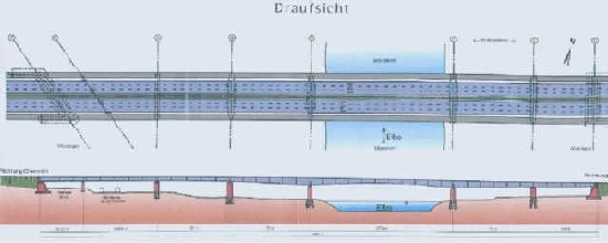
The entire construction project of the 500 m long bridge was divided into 4 phases.
Phase 1:
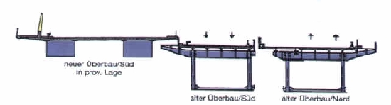
Construction of a new superstructure in a temporary position next to the existing bridge facing toward the south. To that end some supporting pillars had to be built. During that phase all road traffic on the motorway A4 was still going across the old bridge.
Phase 2:
After some reorganization, traffic that was going in one direction was guided across the newly built superstructure in a temporary position, and traffic in the other direction was going across the southern part of the old bridge. Then the northern part of the old bridge was torn down and the northern part of the new bridge was built at its final location.
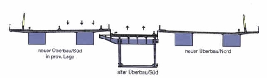
Phase 3:
Traffic that was still going across the old bridge was now led across the newly built norther part of the bridge. Then the southern part of the old bridge was torn down.
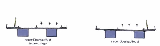
Phase 4:
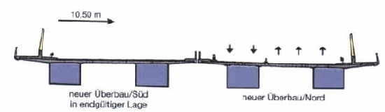
For some time the entire road traffic was guided across the new northern part of the bridge. During this phase the newly built southern part of the bridge was laterally displaced by 10.5 meters and that way put into its final position. Then all temporary elements were torn down and both bridge parts were opened for road traffic.
Measurement task
When construction phase 2 began, but even more importantly during phases 3 and 4, it became necessary to permanently monitor the relative vertical movements of the pillars of the new southern bridge part (in particular one supporting pillar which was located close to the old pillars 2 and 3 as well as the partially reused pillars 2 and 3 in close proximity to the river bank after the southern bridge part had been displaced). It was also necessary to monitor if the superstructure was subject to bending, especially due to the fact that the new bridge part in its temporary position had to cope with full traffic load.
The monitoring system should therefore allow for continuous automatic measurements of any influence on the bridge construction caused by traffic load, wind, air and radiation temperature as well as temperature changes at the bridge construction itself. During the construction phases ‘bridge in temporary position’, ‘tearing down the old bridge’, ‘load test’ and ‘after opening for traffic’ the system was supposed to take a measurement every 30 minutes, during phase ‘displacement of the bridge to its final position’ every 5 minutes.
Equipment Setup
The new deck of the bridge (superstructure south) has two accessible box girders made of steel. The project required six measurement units which were installed inside those box girders above pillars 2 and 3 as well as in the middle of the river between those two pillars, with each pair of units facing toward each other.

In order to avoid any damage to the corrosion-resistant coating, the instruments had to be connected to the steel structure using a special clamping system. The measurement units themselves were connected with water and air hoses. A tripod with a ball-headed bolt and a clamp strap was attached to the instrument’s mounting bracket. Those special tripods allowed for horizontal alignment of the sensors, so that the water hoses could be installed at almost the same horizontal level. That way any possible errors due to density differences could be reduced to a minimum.
Boreholes with a diameter of 32 mm were added to the accessible box girders so that the individual measurement units could be connected with each other. The hoses and data cables were put inside a protective tube which was attached to a taut steel wire. Inside the box girders the tubes were suspended by taut steel wires as well.
During summer time the water hoses were filled with de-ionized water, and during winter time with a mixture of de-ionized water and certain additives. The computer was put into a heated cupboard to make sure that the measuring equipment was able to operate properly even at low temperatures during winter time. The cupboard with the computer could be locked. Measurement results could only be received and changes to the measurement parameters could only be done after a password had been entered. The temperatures of the liquid were measured as well in order to correct the measurement results. Likewise, the temperatures of the box girders’ concrete and metal elements as well as air and radiation temperatures were measured so that the deformation behavior of the bridge construction could be evaluated.
Measurement results
The differences and changes in height of the individual units were recorded in relation to each other and the measurement data was saved in an ASCII file. All relative downward movements of the pillars, the tilting of the pillars perpendicularly to the bridge construction and the bending of the bridge between pillars 2 and 3 could be shown graphically for the entire measuring period. The bending of the bridge was measured directly as a change in height. All recorded data were transmitted to the computer every day and then analyzed with a software.
It can be concluded that the measuring system operated very reliably over the period of one year even under extreme conditions and allowed for a permanent monitoring of the new bridge for the motorway A4 in Dresden.
Some odd occurrences that took place during the measuring period must also be mentioned at this point.
On one occasion a large mobile crane was positioned on top of the bridge as part of a load test. However some structural engineers who calculated the theoretical values which were to be expected using the indicated weight of the mobile crane noticed that there was a deviation of the real measurement values. The riddle could be solved after the mobile crane had been put on a weighing machine again. The mobile crane was considerably heavier and the engineer’s calculated values with regard to the bending of the bridge now corresponded to the real values that had been measured.
Another incident was related to a significant spike in bridge bending close to the middle of the river during nighttime. This occurrence could be resolved subsequently as well. The spike had been caused by a verified truck accident on the bridge.
Literature:
Löbel, K.-H.: Tradition und Gegenwart des Präzisionsinstrumentenbaus in Freiberg; Technische Universität Bergakademie Freiberg, Freiberg 2000
(Löbel, K.-H.: The history and the present state of the manufacture of precision instruments in Freiberg, Technical University Bergakademie Freiberg, Freiberg 2000)